Greetings everyone!
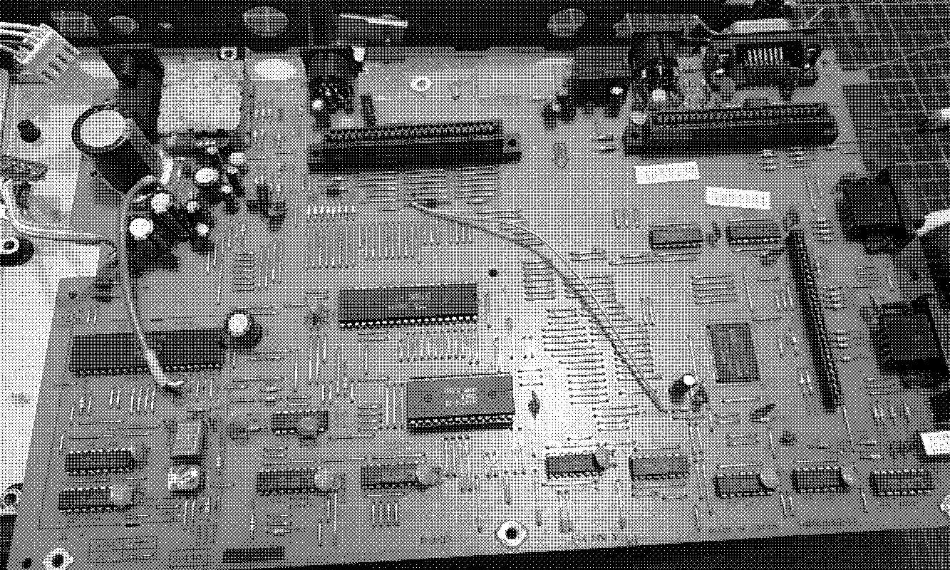
A couple of weeks ago I got a Sony HitBit 10p from a mechanical keyboard enthusiast from the University, a great guy :). He know where to leave MSX things. There was a particular issue: There was no power supply. After changing one power supply for a Sony HB-T7 I thought that it would not be much of a problem. And actually it was not!
I found a tutorial in spanish on how to do this with a phone charger. As you can see in the video, what he does is to use a soldering point below the switch connector to solder a 5v input.
After reviewing a bit the board traces, I saw that the point where the guy from the video soldered was the same as the actual input. So, it lead to the power connector.
In MRC there is information about the power supply and with this I finally understood.
Output:
    DC6V ⎓ 900mA
    AC16V ~ 160mA
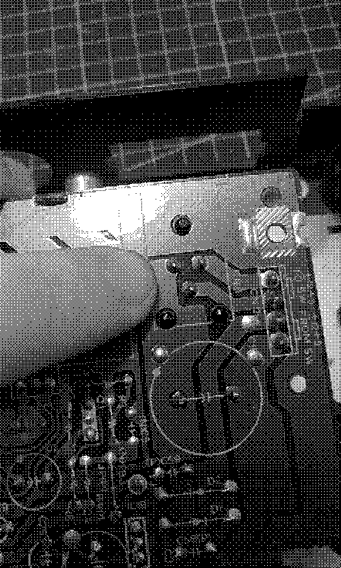
As we can see in this picture, the left pin is the GND, the center pin is the 6V DC input and the left is the 16V AC input.
There is a 16V AC supply that is used to generate at some point in the board the -12/+12V signals. I could not trace where it is converted, because my knowledge on electronics is rather poor. But about the 6V DC, that’s the main power supply for the MSX. As side note, all the MSX runs with 5V and it needs the -12/+12V for some expansions like FMPAC. I do not own any expansions that require this voltage so… I was going to do the same as the guy in the video did.
The thing is, the power supply provides 6V but in the video he uses a 5v supply, so I assume that it is tolerant to undervolting. The same happens with the Casio PV7 machine, as the original power supply had a 10V input but 9V is sufficient to use it. If anyone has more information, please contact me.
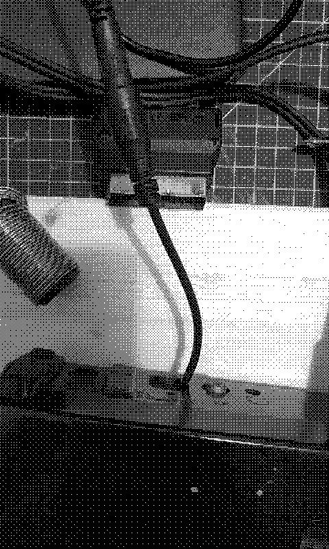
So… the thing was urgent. I had to do it. At 11PM. So I got a barrel jack power switch and desoldered it to have an “el cheapo power connector”.
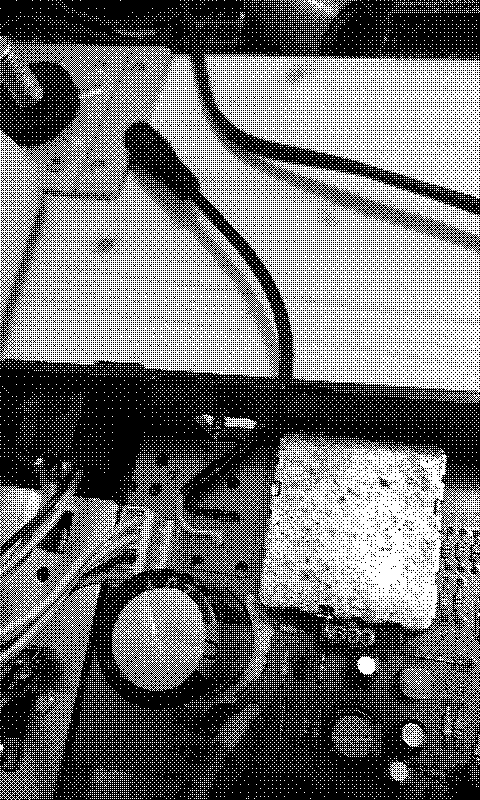
So, I connected the center of the barrel jack (so I can use a modern positive-center power supply) to the 6V input (the center pin from the power connector picture) and the other cable to the GND (the left of the power connector picture). It is really trashy, but it works. I will buy a proper connector ASAP.
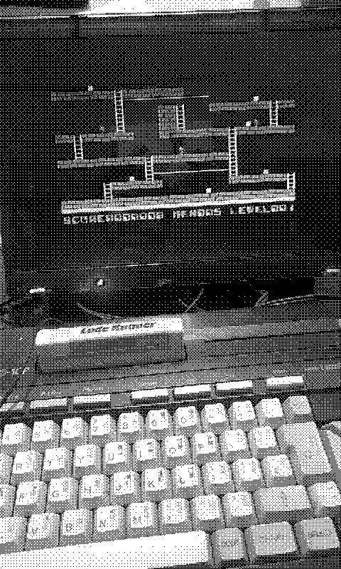
And… I had to test it with the BESTEST game in the world:
And… that it! It works! So now this MSX will start its new life.
At some point, if I am not lazy, I will investigate how the input is used to convert to -12/+12V so that I can remove the components that do the conversion and install a board from MSXMakers that transform 5v into the -12/+12V. I have used it for the Omega MSX and it works pretty well :).
I hope you can fix your MSX too!
